


Designing for Fault-Tolerance
Reza Hajiha /Senior Electrical Engineer /Sharif University of Technology
- Introduction
To achieve high levels of power-system reliability — with the ultimate goal being 24-hour-per-day availability, 365 days per year — some form of power-system redundancy is required, regardless of how reliable the individual power-system components may be [1]. Redundancy, if properly implemented, also provides power-distribution flexibility. By providing more than one path for power flow to the load, the key elements of a system can be shifted from one device or branch to another as required for load balancing, system renovations or alterations, or equipment failure isolation. Redundancy also provides a level of fault tolerance. Fault tolerance can be divided into three basic categories:
- Rapid recovery from failures
- Protection against “slow” power system failures, where there is enough warning of the condition to allow intervention
- Protection against “fast” power system failures, where no warning of the power failure is given As with many corrective and preventive measures, the increasing costs must be weighed against the benefits.
For example, recent developments in large UPS system technologies have provided the capability to operate two independent UPS systems in parallel, either momentarily or continuously. The ability to momentarily connect two UPS systems allows critical loads to be transferred from one UPS system to the other without placing the UPS systems in bypass, thereby maintaining continuous UPS protection of the loads. Continuous paralleling of the two UPS systems, on the other hand, can be used to create a single redundant UPS system from two otherwise nonredundant systems when multiple UPS modules are out of service (because of failures or maintenance).Figure 1.1 illustrates one such implementation.
- Critical System Bus
Many facilities do not require the operation of all equipment during a power outage. Rather than use one large standby power system, key pieces of equipment can be protected with small, dedicated, uninterruptible power systems. Small UPS units are available with built-in battery supplies for computer systems and other hardware. If cost prohibits the installation of a system wide standby power supply (using generator or solid state UPS technologies), consider establishing a critical load bus that is connected to a UPS system or generator via an automatic transfer switch. This separate power supply is used to provide ac to critical loads, thus keeping the protected systems up and running. The concept is illustrated in Figure 1.2. Unnecessary loads are dropped in the event of a power failure.
A standby system built on the critical load principle can be a cost-effective answer to the power-failure threat. The first step in implementing a critical load bus is to accurately determine the power requirements for the most important equipment. Typical power consumption figures can be found in most equipment instruction manuals. If the data is not listed or available from the manufacturer, it can be measured using a wattmeter.
When planning a critical load bus, be certain to identify accurately which loads are critical and which can be dropped in the event of a commercial power failure.
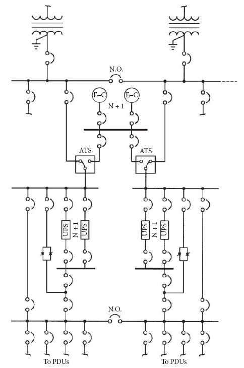
Figure 1.1 Power-distribution system featuring redundancy and high reliability. Of particular interest is the ability to parallel UPS systems as required by operational conditions. [1]
If air-conditioning is interrupted but the Computer equipment at a large data processing center continues to run, temperatures will rise quickly to the point at which system components may be damaged or the hardware automatically shuts down. It may not be necessary to require cooling fans, chillers, and heat-exchange pumps to run without interruption.
However, any outage should be less than 1 to 2 min in duration. Air-cooled computer systems can usually tolerate 5 to 10 min of cooling interruption.
۲.۱ Powers-Distribution Options
There are essentially 12 building blocks that form what can be described as an assured, reliable, clean Power source for computer systems, peripherals, and other critical loads [2]. They are:
- Utility and service entry (step-down transformer, main disconnect, and panel board, switchboard, or switchgear).
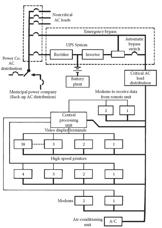
Figure 1.2 An application of the critical-load power bus concept. In the event of a power failure, all equipment necessary for continued operation is powered by the UPS equipment. Noncritical loads are dropped until commercial ac returns.
- Lightning protection
- Power bus
- Facility power distribution
- Grounding
- Power conditioning equipment
- Critical load air-conditioning
- Frequency converter (if required)
- Batteries for dc backup power
- Emergency engine-generator
- Critical load power-distribution network
- Emergency readiness planning
A power system to support a critical load cannot be said to be reliable unless all these components are operating as intended, not only during normal operation, but especially during an emergency.
It is easy to become complacent during periods when everything is functioning properly, because this is the usual mode of operation. An absence of contingency plans for dealing with an emergency situation, and a lack of understanding of how the entire system works, thus, can lead to catastrophic shutdowns when an emergency situation arises. Proper training, and periodic reinforcing, is an essential component of a reliable system.
۲.۲ Plant Configuration
There are any number of hardware configurations that will provide redundancy and reliability for a critical load. Each situation is unique and requires an individual assessment of the options and — more importantly — the risks. The realities of economics dictate that cost is always a factor. Through proper design, however, the expense usually can be held within an acceptable range.
Design for reliability begins at the utility service entrance [2]. The common arrangement shown in Figure 1.3 is vulnerable to interruptions from faults at the transformer and associated switching devices in the circuit. Furthermore, service entrance maintenance would require a plant shutdown. In Figure 1.4, redundancy has been provided that will prevent the loss of power should one of the devices in the line fail. Because the two transformers are located in separate physical enclosures, maintenance can be performed on one leg without dropping power to the facility.
Of equal importance is the method of distributing power within a facility to achieve maximum reliability. This task is more difficult when dealing with a campus-type facility or a process or manufacturing plant, where — instead of being concentrated in a single room or floor — the critical loads may be in a number of distant locations.
Figure 1.5 illustrates power distribution through the facility using a simple radial system. An incoming line supplies the main and line feeders via a service entrance transformer. This system is suitable for a single building or a small process plant. It is simple, reliable, and lowest in cost. However, such a system must be shut down for routine maintenance, and it is Vulnerable to single-point failure. Figure 1.6 illustrates a distributed and redundant power-distribution system that permits transferring loads as required to patch around a fault condition. This configuration also allows portions of the system to be de-energized for maintenance or upgrades without dropping the entire facility. Note the loop arrangement and associated switches that permit optimum flexibility during normal and fault operating conditions.
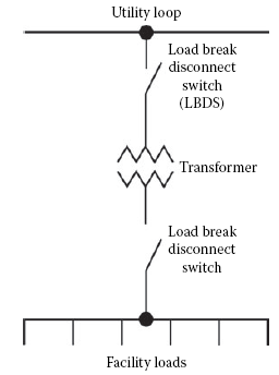
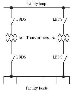
Figure 1.3 Simplified service entrance systems . Figure 1.4 Fault-tolerant service entrance systems.
۲.۳ Plant Maintenance
Maintenance of the facility electrical system is a key part of any serious energy-management effort. Perform the following steps on a regular basis:
- Measure the current drawn on distribution cables. Document the measurements so that a history of power demand can be compiled.
- Check terminal and splice connections to make sure they are tight.
- Check power-system cables for excessive heating.
- Check cables for insulation problems.
- Clean switchboard and circuit-breaker panels.
- Measure the phase-to-phase load balance at the utility service entrance. Load imbalance can result in inefficient use of ac power.
- Measure and chart the power factor of the load. Develop and post a simplified one-line schematic of the entire power network as well as other building systems, including heating, air-conditioning, security, and alarm functions. A mimic board is helpful in this process. Construct the mimic board control panel so that it depicts the entire ac power-distribution system.
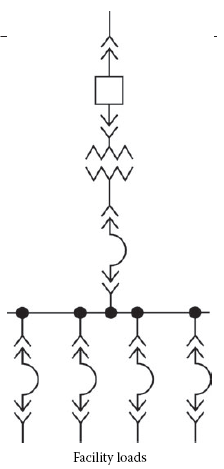
Figure 1.5 secondary plant distributions using a simple radial configuration.
The board should have active indicators that show what loads or circuit breakers are turned on or off, what functions have been disabled, and key operating parameters, including input voltage, load current, and total kVA demand. Safety considerations require that machinery not be activated from the mimic board. Permit machinery to be energized only at the apparatus.
As an alternative, remote control of machines can be provided, if a remote/local control switch is provided at the apparatus.
Environmental control systems should be monitored closely. Air-conditioning, heating, and ventilation systems often represent a significant portion of the power load of a facility. Computer-based data logging equipment with process control capability can be of considerable help in monitoring the condition of the equipment. The logger can be programmed to record all pertinent values periodically and to report abnormal conditions.
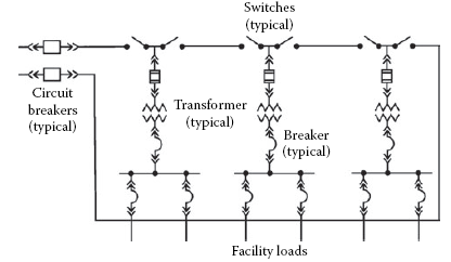
Figure 1.6 A redundant, fault-tolerant secondary plant distribution system.
- References:
- Gruzs, T. M., “High Availability, Fault-Tolerant AC Power Distribution Systems for Critical Loads, Proceedings, Power Quality Solutions/Alternative Energy , Intertec International, Ventura, CA, pp. 20–۲۲, September 2002.
- DeDad, J. A., “Considerations in Designing a Reliable Power Distribution System,” in Practical Guide to Power istribution for Information Technology Equipment , PRIMEDIA Intertec, Overland Park, KS, pp. 4–۸, ۲۰۰۸.
- Download The Article:Paper Designing for Fault-Tolerance


